Thermal Spray Coating


Thermal Spray Coating

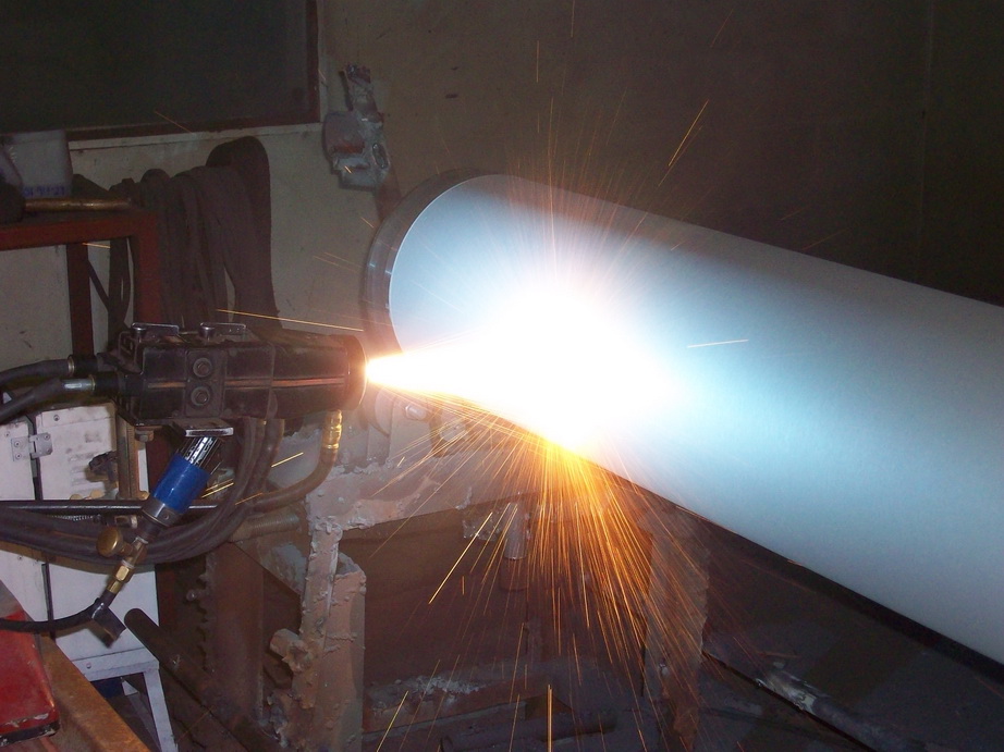
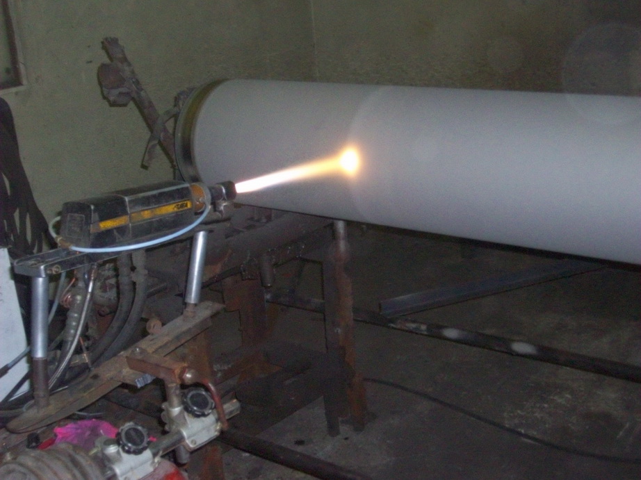
Thermal Spraying is a technique used to produce coatings. The principle of thermal spraying involves melting or semi-melting coating materials and propelling them onto the surface of the workpiece using gas pressure, as illustrated in Figure 1. Upon impact, the material solidifies rapidly, forming a coating. The resulting thermal spray coating features a lamellar structure consisting of overlapping, flattened layers. This structure arises from molten or semi-molten particles spreading upon impact with the surface. The adhesion between particles in the coating primarily occurs through interlocking, forming a mechanical bond as the particles settle and solidify.

The microstructure of a typical thermal spray coating consists of several components (as shown in Figure 2), including layers of molten or semi-molten particles, unmelted particles, oxide inclusions, and voids or pores, referred to as porosity.


Figure 1 Thermal Spray Application Diagram.             Figure 2 Thermal Spray Coating Structure Illustration.


Advantages of Thermal Spray Coating

  1.     A wide range of coating materials can be selected, provided the materials can melt without decomposing when exposed to heat.
  2.     Various techniques or spray guns can be chosen based on the desired properties of the coating.
  3.     Coated workpieces can be re-sprayed after use, even once their dimensions or properties have changed.

Limitations of Thermal Spray Coating

  1.      Workpieces with complex shapes may not be fully coated, as the spray gun nozzle may not reach corners or confined areas.
  2.      Some equipment is expensive, and the spraying process has relatively high costs, requiring careful consideration of cost-effectiveness.

Types of Thermal Spray Coating Applications

1. Flame spray


Flame Spraying (FS) is considered the earliest development in thermal spraying, using heat generated by the combustion of fuel gases and oxygen. Flame spraying is compatible with coating materials in various forms, such as powder, rods, and wire.

The fuel gases used depend on the properties of the coating material and include acetylene, propane, methyl–acetylene–propadiene, and hydrogen. Figures 3–4 illustrate examples of flame spray guns.

Flame spraying is classified as a low-velocity technique compared to more advanced methods developed later. As a result, it is also referred to as Low-Velocity Oxy-Fuel (LVOF) Spraying. This technique is cost-effective, easy to operate, and offers high coating rates and efficiency.

However, flame-sprayed coatings generally have lower bond strength and higher porosity due to the relatively low spraying temperatures, ranging from 2000°C to 3000°C, compared to other techniques. The limited temperature control makes it suitable primarily for materials with low melting points, such as aluminium (Al), molybdenum (Mo), copper (Cu), and zinc (Zn), which are often used for corrosion-resistant coatings.

Common alloys used in flame spraying include nickel-based alloys and bronze alloys. Additionally, certain cermets, such as carbide-nickel alloy composites, are used for wear-resistant coatings. Even ceramic materials, such as aluminium oxide (Al₂O₃) and chromium oxide (Cr₂O₃), can be applied using flame spraying in both powder and wire forms.


Figure 3 - Wire Flame Spray Coating Process [https://www.gordonengland.co.uk/cws.htm]


Figure 4 - Powder Flame Spray Coating Process [https://www.gordonengland.co.uk/cps.htm]

2. Arc spray


Arc Spraying (AS) is a thermal spray process that uses heat generated by an electric arc between two electrodes. The coating material must be in the form of electrically conductive wire, which can be a metal alloy or a cored wire containing ceramics at its core. The outer layer of the wire, made of metal or alloy, enables conductivity and allows the arc to occur.

Unlike other techniques, arc spraying does not rely on external heat sources such as flames or plasma. Instead, the heat and melting occur directly within the coating material. This happens when the two wires with opposite charges touch at their tips, creating an arc. The molten particles at the wire tips are atomized by high-pressure gas and propelled onto the workpiece surface, where they cool and solidify to form the coating. This process is illustrated in Figure 5.

Arc spraying offers several advantages over flame spraying. Coatings produced by arc spraying have higher bond strength, typically exceeding 1000 psi. Additionally, less heat is transferred to the substrate since there is no direct flame contact, reducing the risk of thermal damage. Arc spraying is also more cost-effective, as it does not require fuel gases or oxygen.

One of the key advantages of arc spraying is its high deposition rate, capable of reaching up to 50 kilograms per hour for nickel-based alloys. This makes arc spraying particularly efficient for large-scale coating applications. 

Figure 5 - Arc Spray Coating Process [https://www.gordonengland.co.uk/aws.htm]

3. High Velocity Oxy-Fuel Spray : HVOF Spray


High Velocity Oxy-Fuel Spraying (HVOF) is an advanced thermal spraying technique evolved from flame spraying, utilizing heat generated from the combustion of fuel gas and oxygen. The key difference between flame spraying and HVOF is the location of combustion: in flame spraying, combustion occurs outside or at the tip of the spray gun, whereas in HVOF, combustion happens inside the gun, within the combustion chamber.

A critical design element of HVOF is the nozzle, which extends from the combustion chamber in the form of a small, narrow, and elongated tube (as illustrated in Figure 6). This nozzle design significantly increases particle velocity. As gases combust in the chamber, they expand and are forced through the narrow nozzle, creating high pressure. This causes the gas to accelerate to supersonic speeds.

In HVOF spraying, powder can either be fed into the combustion chamber or directly into the nozzle, depending on the gun design. The elongated nozzle allows the powder to be heated for a longer time, and the high pressure propels the particles at speeds up to 800 meters per second.

The fuel gases commonly used in HVOF include propane, propylene, methyl-acetylene-propadiene (MAPP), and hydrogen. Liquid fuels, such as kerosene (also known as paraffin), can also be used, with air serving as the oxidizer.

This combination of high temperature and high velocity makes HVOF ideal for producing dense, wear-resistant coatings with strong mechanical bonds, suitable for applications requiring superior surface protection.

Figure 6 - HVOF Coating Process [https://www.gordonengland.co.uk/hvof.htm]

4. Plasma Spray


Plasma Spraying (PS) utilizes the intense heat from a plasma flame, which can reach temperatures as high as 12,000°C. This technique is particularly suitable for spraying ceramic materials, as most ceramics have high melting points. The heat in the plasma is generated by passing gases, such as argon (Ar) or mixtures like Ar+H₂, Ar+He, or Ar+N₂, through a cathode made of tungsten (W) and an anode made of copper (Cu), both cooled by water.

When an electric arc is initiated between the electrodes using high-frequency direct current (DC), the gas ionizes, generating heat that causes it to expand into a high-pressure, high-temperature plasma. The plasma jet travels at high velocity through the nozzle of the spray gun. As the coating powder is fed into the plasma jet, it melts and is propelled towards the substrate, forming a coating upon impact (as illustrated in Figure 7).

Argon (Ar) is the primary gas used for plasma generation because it is chemically inert and a monatomic gas. Its single-atom structure allows it to achieve higher gas velocities compared to diatomic gases. The heat capacity of the plasma can be enhanced by adding diatomic gases like nitrogen (N₂) or hydrogen (H₂), which have higher thermal conductivity. In some cases, a mixture of Ar and He is used to further increase thermal efficiency. The design of the plasma gun, particularly the shape and size of the cathode and anode, plays a crucial role in controlling particle velocity and temperature based on the gas mixture used.

The spray distance is another important factor in plasma spraying. Since plasma jets have very high temperatures and velocities, the distance must be sufficient to prevent excessive heating of the substrate. However, it must not be too long, as the particles may cool and lose velocity before reaching the surface.

The most common form of plasma spraying is Atmospheric Plasma Spraying (APS), where the process is carried out in open air. However, during APS, molten particles can react with atmospheric oxygen, forming oxides that affect the structure and properties of the coating. To address this issue, plasma spraying systems have been developed for vacuum environments, called Vacuum Plasma Spraying (VPS) or Low-Pressure Plasma Spraying (LPPS). In these systems, the air is evacuated to pressures between 0.001–0.01 Pa and replaced with inert gases, such as argon. These conditions reduce oxygen levels to less than 30 ppm, minimizing oxidation and ensuring high-quality coatings.

Figure 7 - Plasma Spray Coating Process [https://www.gordonengland.co.uk/ps.htm]

Reference:

Journal: "เทคโนโลยีการพ่นเคลือบด้วยเปลวความร้อน" "Thermal Spray Coating Technologies"

Author: Professor Sittichai Wirojanupatump

Translated to English for this article by Advanced Surface Technologies Co., Ltd.